Adventures in Microcontroller Circuit Debugging
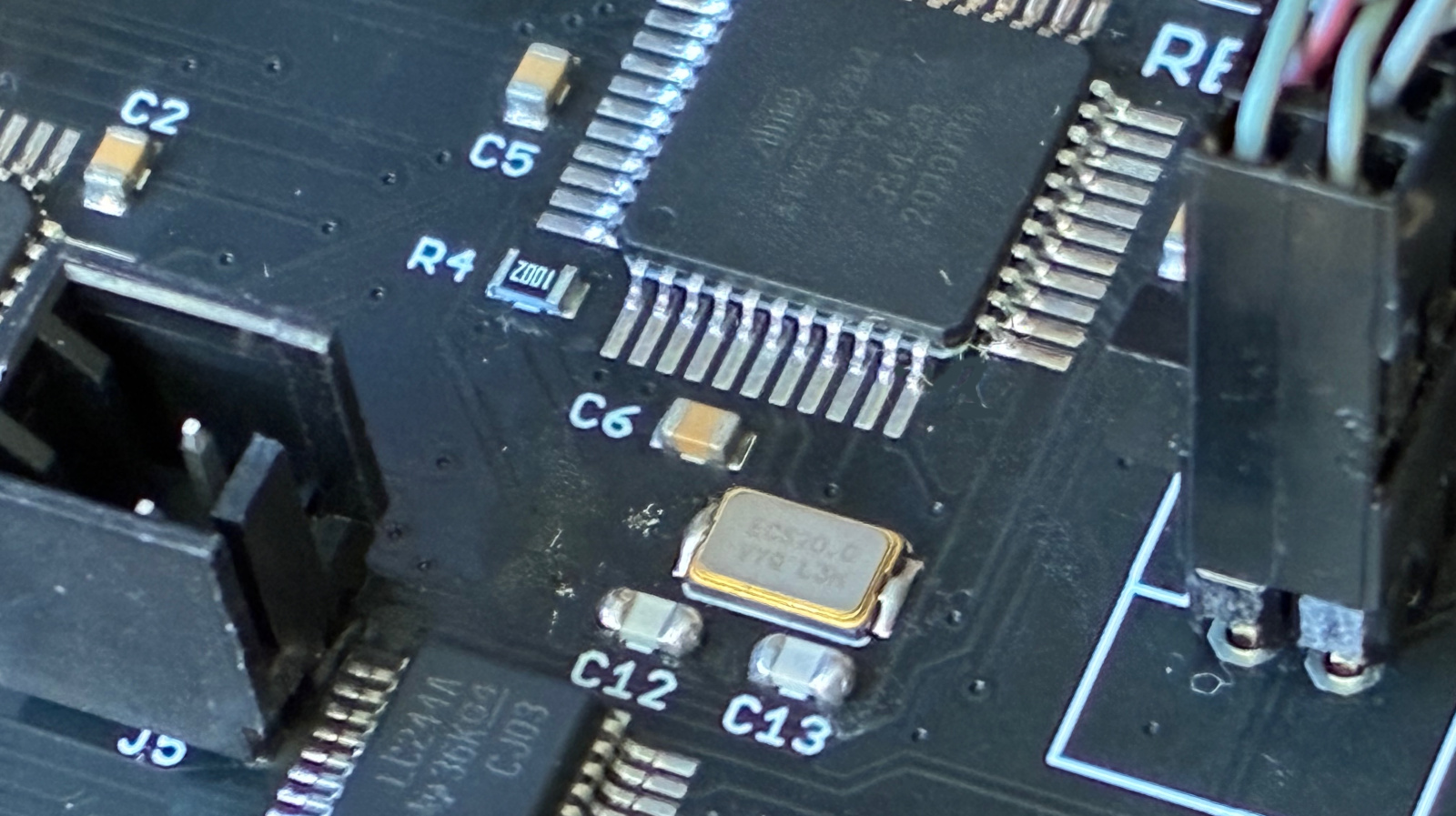
How do you go about troubleshooting a misbehaving microcontroller circuit? A few months ago I manufactured a new batch of Floppy Emu disk emulators. A number of them failed QA at the factory, with a set of symptoms that I’d never seen before in all my years of developing this device:
- Most of them simply wouldn’t boot up at all, despite verifying that power was good and the mcu was correctly programmed.
- Some exhibited “haunted” behavior, seemingly jumping to random sections of the mcu program code, outputting messages on the display that made no sense given the context.
- One of them appeared to work in slow motion, with LED blinking and display updates noticeably more sluggish than normal.
This was odd, to say the least. I have a lot of experience with the ATMEGA1284 microcontroller and the Floppy Emu circuitry that surrounds it, and I’ve become an expert at guessing what’s wrong based on the symptoms of misbehaving boards. These were all new and bizarre symptoms to me. Might they arise from different problems, or could they all point to one common underlying issue?
My intuition suggested some kind of systematic assembly problem. My contract manufacturer used a new subcontractor for this batch of Floppy Emu boards, so maybe a silent change to the process caused an unexpected issue? Parts substitution? Bad parts? Counterfeit chips? These QA failures sat in a pile on my desk for months, waiting for answers.
Probing, Poking, and Theorizing
Yesterday I finally decided to concentrate on the “won’t boot” devices, since that seemed like the most tractable problem. I put a few boards in a test harness, and connected power and a hardware debugger. The power supply voltages looked good. No obvious soldering problems were evident, but just to be sure I reflowed the solder on a few boards, without seeing any improvement.
On many of the boards, the hardware debugger could talk to the microcontroller and I was able to confirm the chip was correctly configured and programmed, but the program didn’t seem to actually run. At power-up the boards did… nothing. And with a smaller number of the boards, the debugger could not communicate with or even detect the chip. What could cause these symptoms? I brainstormed:
- Bad power. Seemingly ruled out by my measurements.
- Misprogrammed chips. I confirmed the configuration and reprogrammed several, without improvement.
- Bad chips.
- Chips stuck in reset.
- Clock problems.
- Problems with other circuit components (SD Card, CPLD, etc) causing electrical or program failures.
A batch of bad microcontroller chips seemed like the most likely explanation, so I desoldered the ATMEGA1284 from a board and replaced it with a new one from my stash. But after configuring and programming the chip, the board behaved the same as before, refusing to boot. That seemed to rule out problems with the chips themselves.
In the Floppy Emu program code, when the device first powers up, there’s some communication with the SD Card and the CPLD that happens before anything is drawn on the device display. I suspected that something might be going wrong during those steps, causing the program to freeze or crash and resulting in a blank display. To test this, I modified the program to blink the status LED twenty times as proof of life at the start of main() before doing anything else. Yes, with all the hardware tools at my disposal, I was back to caveman debugging with a blinking LED.
But there was still no joy, no LED blinking, no apparent program activity at all during power up. What the hell? Here I had a good microcontroller with good power, confirmed programmed correctly, in a circuit and board design that’s been in successful use for years. It wouldn’t even blink an LED. Since the blinking should have happened as the very first step of the program, its absence mostly seemed to rule out explanations related to failed interactions with other circuit components like the SD Card. So I focused in on the reset signal and the clock, the only two possibilities that I had left.
Clock Crystal Mysteries
Floppy Emu’s microcontroller uses an external 20 MHz crystal for speed and precision, but it also has an internal built-in 8 MHz oscillator. This particular board was still communicating OK with the hardware debugger, so for grins I tried changing the chip’s fuse configuration to select the internal 8 MHz oscillator as the clock source. Lo and behold, it worked! The device booted up and appeared to run normally, although obviously at only 40 percent of normal speed. I confirmed the same result with a few other boards – when I was able to get debugger communication and change the clock source to the internal oscillator, the board would boot. This wasn’t a fix, since the Floppy Emu won’t actually work correctly with an 8 MHz oscillator, but it was proof of major trouble with the external clock crystal.
If an external crystal isn’t working reliably, the microcontroller won’t have a reliable clock source. It will probably fail to run at all, or else act super glitchy. It will also cause problems with debugger communication. This all sounds a lot like my observed symptoms.
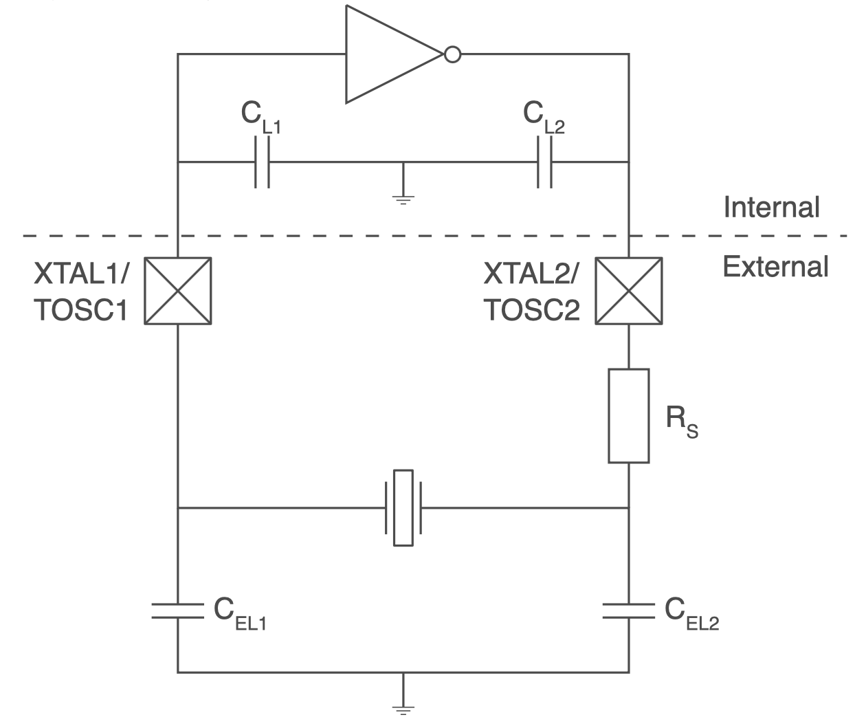
So let’s talk about this crystal oscillator circuit. Like almost all microcontrollers, the ATMEGA series has built in amplifier hardware to drive an external piezo crystal and force it to oscillate, using a circuit that I believe is called a Pierce Oscillator. I should know more about the theory of operation, but I’m mostly ignorant. What I know is that you connect the crystal’s two terminals to two ATMEGA pins using the shortest PCB traces that are practically possible, and add two external capacitors with values in the picofarad range, whose values are determined by a formula, and then everything works.
Investigating a bit further, I observed that all of the problem boards used a different crystal manufacturer than I have used previously. That’s fine, it shouldn’t have been an issue, but it seemed important given the circumstances. Previous editions of the board used this NDK crystal, but these troublesome boards substituted a similar ECS crystal. Both used the same physical footprint and advertised an 8pF load capacitance.
Speculations and Next Steps
As of today, that’s as far as I’ve gone with direct debugging, but I’m continuing to search for a smoking gun explanation. Maybe I got a batch of bad crystals? Possibly, and I can try reworking a board and replacing its crystal, but that explanation seems not very likely to me.
What about those two capacitors that form part of the oscillator circuit? Their values are important to the oscillator operation, and if the value is too far off from the optimal value, then the crystal won’t oscillate correctly or won’t oscillate at all. These tiny SMD capacitors bare no markings, so there’s no way for me to confirm visually that the capacitors are the correct ones. Maybe the subcontractor used the wrong value of capacitors on some boards? Speaking of which, what is the correct value?
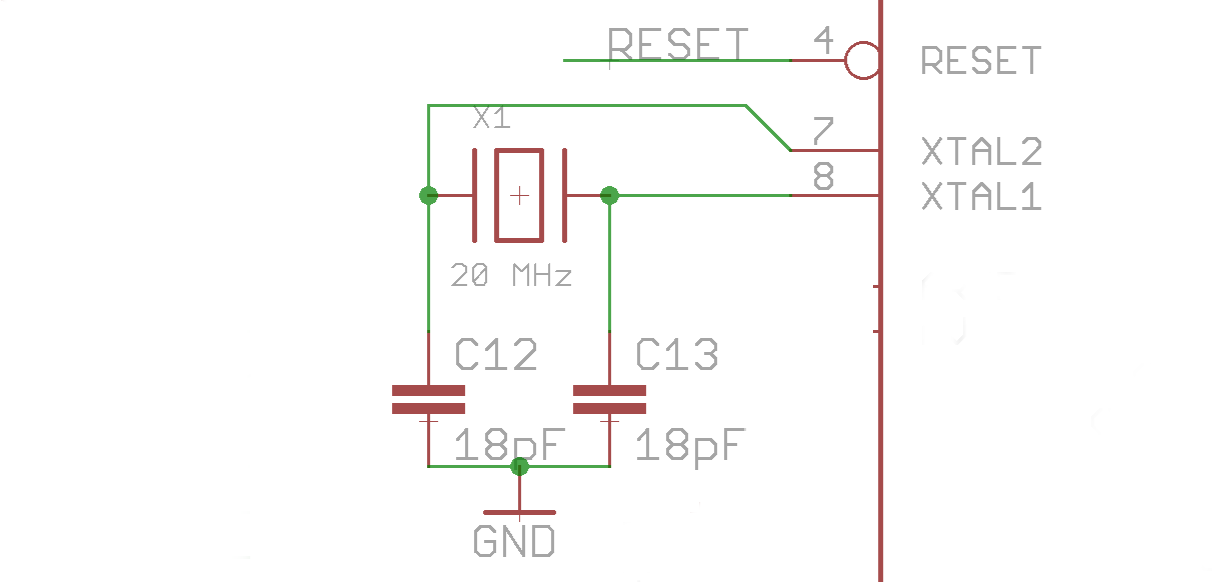
Here we enter into a bit of Pierce Oscillator analog voodoo that I don’t understand very well. The correct value of the two external capacitors is given by the formula Cext = 2 * (Cload – Cstray). Cload is the crystal’s load capacitance: 8pF in this case. Cstray is a measure of the stray capacitance of the microcontroller pins and PCB board traces. There’s no simple way to measure this directly, but for short traces on a two-layer PCB, I’ve seen estimates around 3pF to 5pF. Let’s call it 4pF. So Cext = 2 * (Cload – Cstray) = 2 * (8pF – 4pF) = 2 * (4pF) = 8pF. In theory then, I should have two external 8pF capacitors paired with the clock crystal. In reality, the capacitors are 18pF.
18pF external capacitors. I don’t remember how I originally specified this value; it’s lost in the mists of time during Floppy Emu’s initial development phase. But looking at it again now, it certainly seems “not ideal”. The oscillator circuit can be fairly forgiving and the ATMEGA driver amplifier can work over a broad range of capacitance values, which is probably why I never noticed an issue before. But 18pF is not mathematically correct. My guess is that the oscillator circuit has been operating close to the margins, and now there’s something different enough about this ECS crystal, its ESR or stray capacitance maybe, that pushes the circuit far enough out of its comfort zone that it stops working entirely.
So now what? How can I confirm this theory and fix the issue? One possibility is modifying the ATMEGA’s crystal driver behavior by changing a fuse setting. I normally use the low-power crystal oscillator mode, which applies a driving voltage in the millivolts range, but there’s also an option for full-swing crystal oscillator. In theory this setting should work better in cases like this where the external capacitors are outside the optimal range of values. To test this, I altered the fuses on one board to enable the full-swing oscillator behavior, and… it didn’t work. The board still wouldn’t boot up, and it also stopped communicating with the debugger, so it’s now effectively a brick.
That leaves me with the possibility of reworking the boards and swapping the external capacitors for 8pF replacements. Or maybe 10pF or 12pF if I want to stay closer to the original design value, since problems can also arise if the value is too low as well as if it’s too high. Unfortunately my workshop doesn’t stock any appropriate capacitors in that range. I’ve ordered a variety of values to use for testing, so the conclusion of this mystery will need to wait until then. Stay tuned…

 点赞
点赞 收藏
收藏 点踩
点踩 分享
分享