PDS – the Programmers Development System – Part 7

After the final successes of the past post, I thought it would be worth formally building a diagnostic module that can be used to help debug the system should the need arise.Part 1 – Introduction, background and some initial reverse engineering.Part 2 – A closer look at the PC ISA Interface card.Part 3 – Remaking the target interfaces.Part 4 – Building the boards.Part 5 – Getting everything running (first, unsuccessful attempt).Part 6 – Some serious diagnostics and a breakthrough (at last)!Part 7 – Diagnostic module PCB.
Find it on GitHub here: github.com/diyelectromusic/PDS_Remake
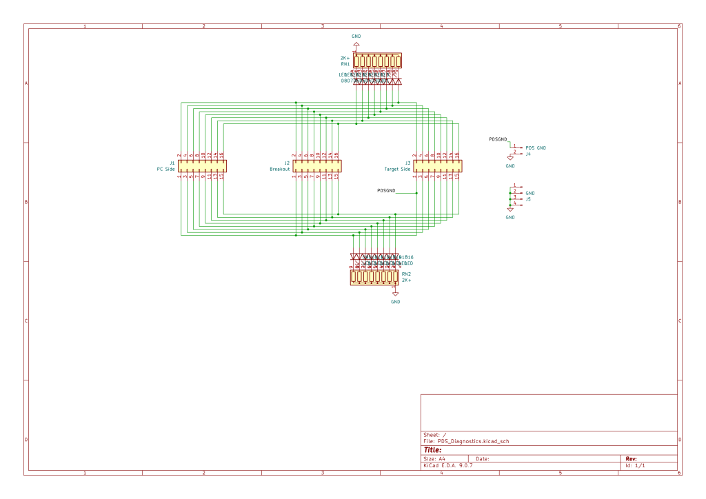
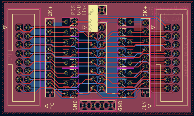
Diagnostic Module Design
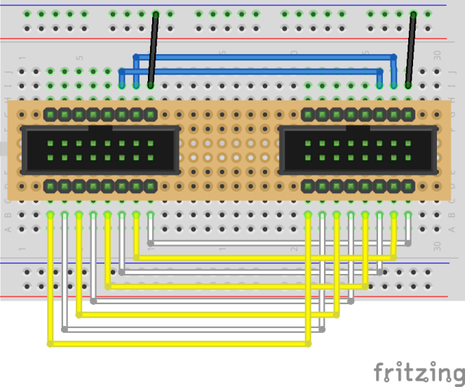
This is a reimplementation of the breadboard diagnostic breakout used in Part 6:
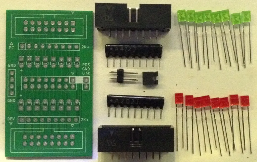
But I’m building it all onto a PCB and want to add built-in LEDs. One thing to watch out for is the current draw as there could be up to 16 LEDs on at any one time.
The 74LS245 buffer for the data lines on the target board will often be driving the 8 data LEDs, so from the datasheet we can see a sink current of 24mA and source current of 15mA and I believe a total supply current of between 70 and 95mA depending on the state of the outputs. So that will be limiting me to around 10mA per LED.
From the other side, the LEDs will be driven by the Intel 8255, but through a series of 74LS244 buffers which seem to have a very similar spec to the 245s used at the target end.
The control lines at the target end are driven from the Z80 PIO via a 74LS04. That is a little more problematic as it appears to have an asymmetric current specification, being 0.4mA for a HIGH output and maybe up to 16mA for a LOW output. 0.4mA is really not very much for an LED…
Some resistor “ball parks” for a 5V powered circuit for a variety of forward voltages of LEDs:
Forward Voltage
Resistor
Current
1.7V
1K
3.3mA
1.7V
4K7
0.7mA
2.0V
500R
6.0mA
2.0V
1K
3.0mA
2.0V
2K
1.5mA
2.0V
4K7
0.7mA
2.2V
1K
2.8mA
2.2V
2K
1.4mA
2.2V
4K7
0.6mA
We can see that none of the…

 点赞
点赞 收藏
收藏 点踩
点踩 分享
分享