Billions of triangles redux

In early September, NVIDIA released an update to their vk_lod_clusters open-source sample, that - among other things - featured a new impressive Zorah scene as a glTF file. The demo showcased the application of new driver-exposed raytracing features, specifically clustered raytracing, in combination with Nanite-like clustered LOD pipeline - allowing to stream and display a very highly detailed scene with full pathtracing. Naturally, this piqued my curiosity - and led me to spend some time to improve support for hierarchical clustered LOD in meshoptimizer.
… Wait, this sounds familiar.
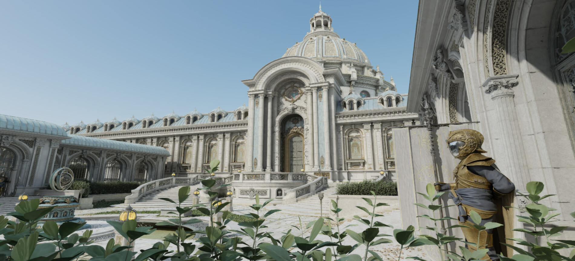
Indeed, the first version of a standalone Zorah scene, as well as the foundational driver components for clustered RT, actually released last year! I’ve written about the journey to get that scene to process quickly in Billions of triangles in minutes. However, the vk_lod_clusters sample has made significant progress since last year, the scene got updated with full attribute set and texture data, the renderer is using path-tracing and looks beautiful, and the processing mostly uses meshoptimizer’s clusterlod.h. Because I did spend some time to improve aspects of this in meshoptimizer, I figured it would make sense to do a writeup, focusing a bit less on processing time now and more on other aspects. Reading the previous article is not required but would probably help understand this one better.
glTF compression
The first thing that you would notice is that the new scene is on a similar scale (1.6B triangles) and comes with a hefty 70 GB download - which should be expected, as it now has a lot of textures! But if you look at just the glTF scene data, the 2025 version was ~36 GB, and the 2026 version is ~32 GB. The overall amount of geometry did not change very much, so this should be surprising as the old scene had just the position data on most of the meshes and should have been noticeably smaller. Indeed, NVIDIA now provides a new version of the original, attribute-less and texture-less, scene, which is just 9 GB.
This reduction is due to the new glTF scenes using meshoptimizer compression extensions, namely EXT_meshopt_compression. This extension exposes support for vertex and index compression; note that vertex data is compressed using an older, “v0” vertex format. The vertex codec has been upgraded with v1 since, which provides further gains in compression ratios and decompression performance, and is supported in a new extension, KHR_meshopt_compression. Since KHR variant was only standardized in early 2026, it makes sense that the assets use the previous version - but we’ll look at both for completeness.
The extensions expose the vertex and index compression but leave a lot of room for the processing tools to organize the data or choose the compression characteristics at will; unlike some black-box “one mesh at a time” formats, meshoptimizer formats are defined on arrays of bytes representing vertex or index data. For vertex data, the compressor itself is lossless and will perfectly reproduce the original byte sequence; however, you can also use additional layers underneath it that would make it lossy, either by using pre-quantized data when glTF geometry accessors support it, or by using “filters” which compress the data with a little bit of lost precision which allows to gain extra compression ratios. The way the meshes reference the arrays is also up to the tools that prepare the data: some tools may decide to use separate buffers for individual meshes, and some may choose to combine them.
Typically, for the last-mile delivery scenarios - e.g. producing a glTF file that will be rendered directly - you’d want to use the lossy compression (see the appendix at the end) and tune the precision to the level that is required for display; that would give you the smallest output file. But in case of the Zorah scene specifically, the scene we’re dealing with is merely an intermediate file - the actual clustered LOD processing will significantly change the precision characteristics in a way that can be tuned later. So it makes sense that the Zorah glTF scene only uses the lossless option. Let’s look at how effective it is.
Because the files are using v0 (EXT) compression, I’ve run stats on the scene as well as what switching to v1 would achieve, and got the following numbers; “v0” is what is stored on disk in the downloaded file at the moment, “raw” is what the scene would look like once decompressed.
| Category | Raw | v0 | v1 (recompressed) |
|---|---|---|---|
| Positions | 14.3 GB | 9.1 GB (63.5%) | 8.9 GB (62.1%) |
| Attributes | 30.1 GB | 21.6 GB (71.8%) | 20.5 GB (68.2%) |
| Indices | 18.9 GB | 1.9 GB (10.1%) | 1.9 GB (10.1%) |
| Total | 63.3 GB | 32.6 GB (51.5%) | 31.3 GB (49.5%) |
So overall on the entire file we get about 2x compression for geometry; indices compress quite well, and the positions and attributes compress a bit less well. Using v1 vertex format would gain a few extra percentage points of compression ratio (and would decode faster).
Now, you may ask - do we even need to compress this file, given that it’s not the final delivery format? The file we download is compressed with a general-purpose lossless compressor, so why bother? There’s two things to say about this.
First, from the processing time point of view, this allows us to reduce the cost of reading the scene from disk compared to either a raw or a hypothetical representation where we use a compressor like Zstandard to keep the files compressed on disk. Decoding vertex or index data runs at multiple gigabytes per second of output data on a single core; as I’ve written in the previous article, the processing is massively multi-core, so our aggregate decompression throughput on 16 cores is “a lot”. The way this is integrated into the processing is that the vertex/index streams for each mesh are compressed independently and decompressed before processing each mesh; as a result, decompression takes under 1% of total processing time, runs fully in parallel, and reduces the size we need to read from disk 2x.
Second, this might result in a smaller file compared to using general-purpose compressors. If we instead used Zstandard (at level 6 in this case), we’d get a larger file, that would also decompress more slowly - either decoder is noticeably faster than Zstandard. What’s more, if you wanted to further reduce the file size, you could additionally compress the encoded bytes with Zstandard again - for an even smaller size! You would have to decompress the file twice - first decompress the encoded bytes using Zstandard, and then decompress the original bytes using meshopt_decode*. However, because Zstandard would need to decompress less data, generally the resulting decoding would still be faster than just using Zstandard alone.
| Raw | v1 | Raw + Zstd | v1 + Zstd |
|---|---|---|---|
| 63.3 GB | 31.3 GB (49.5%) | 38.0 GB (60.1%) | 27.4 GB (43.3%) |
This seems like an unusual property; normally, you should not be able to compress compressed representations! But this is an explicit design point. Instead of implementing the entire featureset of a modern lossless compressor, meshoptimizer codecs focus on parts that lossless compressors, especially faster ones, often don’t model, but try to keep the output stream in a format that is amenable to both fast decoding and further post-compression. This is nice from the versatility point of view - for example, maybe you want to use LZMA as a post-compression layer, which is impractically slow to decompress at game load time, but you could decompress it at install time instead, and just leave the raw meshopt-compressed files on disk.
Ultimately the best balance depends on the data characteristics, and, importantly, the speed of the underlying media. Part of the motivation for the meshoptimizer codecs originally was just that SSDs were becoming unreasonably fast. If your SSD can read many gigabytes per second, you might need many cores to actually save time when streaming assets from disk when using slower compression algorithms; and some compression algorithms simply can’t get there at all as they are too slow. Instead of aiming for a maximum possible compression ratio, meshoptimizer codecs are designed for extremely fast decompression, and are flexible enough that the resulting size can be dialed further with layered compression.
It probably feels like all of this is not directly related to clustered LOD… and indeed it’s not :) it was just an excuse to write about some aspects of mesh compression that happened to be used in Zorah! Let’s talk about the more relevant parts of the processing and runtime.
Processing improvements
The rest of the processing proceeds largely as I’ve written about it last year. A slightly modified version of clusterlod.h is used in vk_lod_clusters and the pipeline itself is as before - split the input mesh into clusters, partition clusters into groups, simplify each group preserving boundary, split the new group into more clusters, rinse and repeat. For runtime LOD selection, clusterlod.h now provides helper utilities to build a BVH over the DAG (clodBuildHierarchy), which can be used to quickly select the clusters that are at the correct level of fidelity, as described in the original Nanite presentation.
Because the scene now has attributes, they need to be communicated to the simplifier so that it can compute the error that fully reflects the appearance change. Each attribute has a scalar weight, and is weighted according to its impact over the surface that it’s changing across. This is using attribute-aware simplification (meshopt_simplifyWithAttributes) which has been available for a few years, and the initial version of clusterlod.h exposed it too; one new improvement to the metric is noted below, but otherwise not a lot has changed with attributes themselves.
When doing cluster partitioning, clusterlod.h uses spatial information by default to improve partitioning and also has an additional option, partition_sort, which sorts partition by Morton order, which makes the entire DAG more spatially coherent; this is helpful for streaming locality. Additionally, the spatial clusterizer (meshopt_buildMeshletsSpatial) is now faster due to strategically placed prefetches, and group partitioning (meshopt_partitionClusters) has seen several improvements over the last couple releases, resulting in faster partitioning and more spatially coherent output. All of this improves DAG shape and streaming behavior. There were also a couple small tweaks for rare corner cases like empty simplified output in clusterlod.h.
Additionally, between the last few meshoptimizer releases, including the new 1.3 release, simplification has seen a few improvements; most importantly for clusterlod.h, permissive mode now has more consistent and correct behavior and has been marked as stable, and attribute error can now be clamped to avoid overly pessimistic LOD selection. Let’s talk about these in a little more detail.
The simplifier in meshoptimizer is driven by topology and by default, expects a reasonable number of attribute seams, which are automatically identified and honored during collapses. This is great when the input mesh has a fair amount of smooth surfaces, but on meshes with many seams leads to the simplifier eventually getting stuck. This is a problem for hierarchical LOD schemes as they rely on high detail source meshes and expect them to be simplified all the way to, ideally, just a single cluster. Additionally, some features of the simplifier that are effective at reducing topologically complex detail, like component pruning, have to be disabled in clusterlod.h as they only work when given the entire input mesh. clusterlod.h does have a fallback in this case using the “sloppy” simplifier (meshopt_simplifySloppy), but that simplifier results in low-quality output that disregards attributes completely. Last year, permissive mode was added to have an alternative mode of operation where topological restrictions are mostly waived.
In that mode, which is enabled by adding meshopt_SimplifyPermissive flag if you use the library directly, it’s important that attributes with discontinuities are given to the simplifier for attribute-based weighting, and that the output error is used during LOD selection; simply using a fixed triangle count budget does not guarantee reasonable appearance. This mode also allows for selective discontinuity protection by tagging vertices on critical seams, which Zorah does not use. Importantly, permissive mode had a few limitations around how it would evaluate and perform edge collapses, and the initial implementation also was restricted around geometric borders - as the logic processing them was not carefully updated in the presence of discontinuities.
These restrictions have now been lifted; this does result in some changes in behavior, but the net effect is that models would typically simplify further in permissive mode, which generally speaking improves the resulting quality. On Zorah, the sloppy fallback is now taken for ~0.01% of simplified groups which seems reasonably benign.
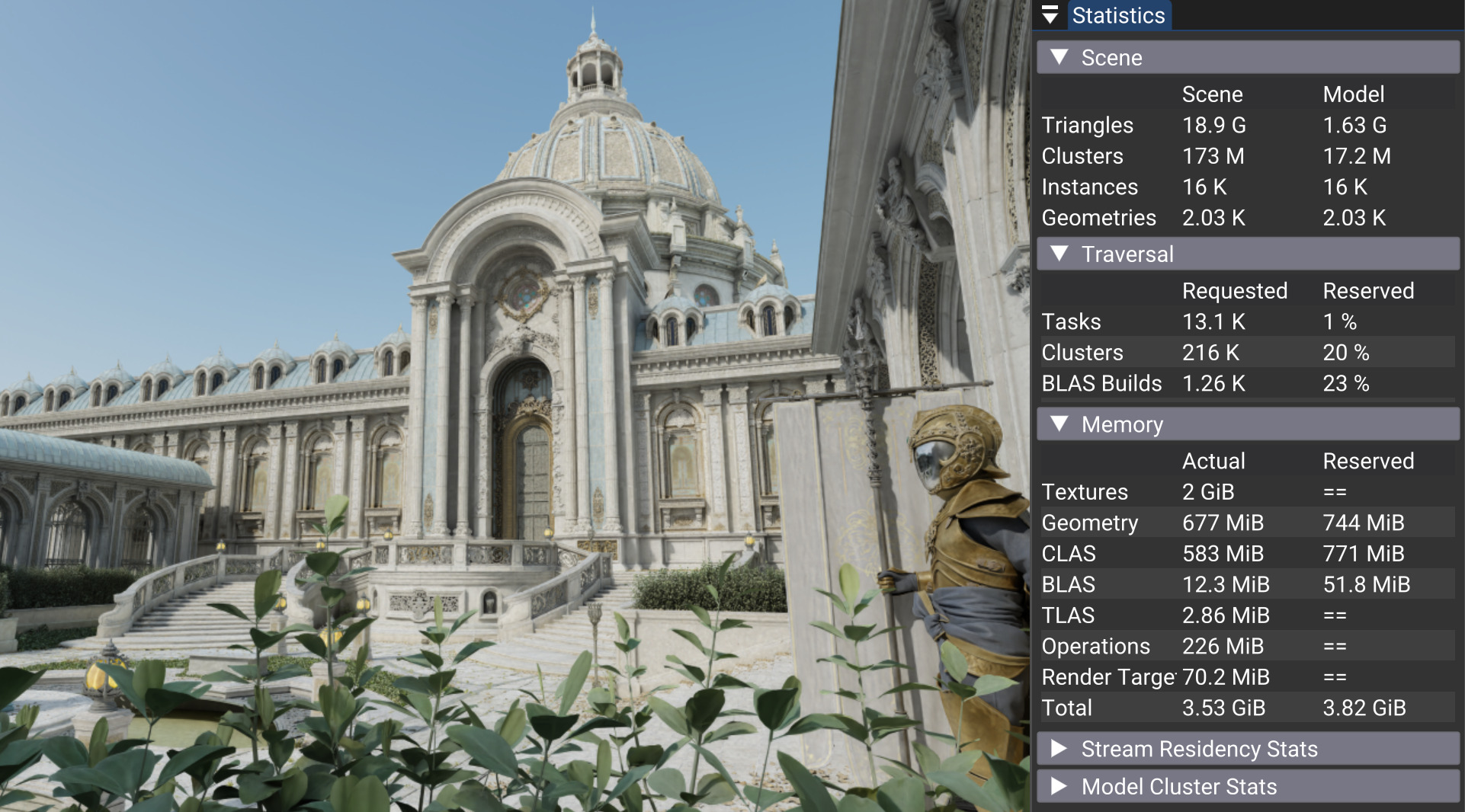
Simplification quality wasn’t the only problem; the other one was memory. The GPU I use is GeForce RTX 5070, with 12 GB VRAM - not the fastest or the largest GPU, but I like it because it keeps my system quiet, and I don’t play games on my desktop anyway. However, between a fairly large screen resolution, a couple gigabytes taken by the various Wayland surfaces for all the open processes, and the need to accommodate the texture pool, I’ve initially struggled with fitting the scene in memory. The requirements for the geometry pool seemed pretty severe; the demo allows configuring three distinct pools, for textures (maxtexturemegabytes), geometry (maxgeomegabytes) and CLAS (maxclasmegabytes); the latter refers to cluster-level acceleration structures which is the bulk of the RT BVH data when using the new clustered raytracing extensions. I’ve sized all three pools to 2 GB, which limited the memory consumption to a bit over 7 GB once all extraneous allocations were accounted for; but, 2 GB was clearly not quite enough for the geometry pool as the flythrough would often run out of the streaming budget.
Importantly, the error values simplifier produces during simplification process are controlling the streaming process; the sample will stream in geometry up until the DAG cut that needs to be rendered matches the error thresholds from the current camera view. If a cluster error is higher than necessary, a higher resolution version of it will be streamed in even if using it as is would not be noticeable - resulting in higher memory consumption and, eventually, exhausting the streaming pools.
Eventually I’ve tracked this to a combination of factors involving attributes. There were some bugs in the sample code that fed incorrect attribute data to the simplifier, which resulted in some clusters having unrealistically high error. Unfortunately all of this is difficult to debug; when you feed invalid data into a complex algorithm that uses that data to, ultimately, drive heuristics and imperfect models, and get the wrong answer - was the bug in the data, or in the models? In this case it turned out that the answer was, both! Because, while fixing the bugs resulted in more reasonable streaming behavior and allowed a more comfortable fit within the budget, we could still go further. Over the last few years I’ve occasionally hit cases where the attribute simplification would end up producing geometry that seemed a little too detailed. The reproduction cases were few and far between; this time, I coincidentally found a few concrete examples a few weeks before looking into Zorah, when working on potential improvements to permissive mode (that did not pan out for now); and, lo and behold, with Zorah I seemed to have found another case like that!
Last year I’ve added an experimental simplify_error_edge_limit option to the cluster evaluation following some discussions; the idea was, if the error the simplifier returns is abnormally high for some reason, we could limit the error based on the triangle size in the cluster. Zorah initially ended up having to use this to mitigate the issues with selecting clusters that were too highly detailed; however, it by itself was not that impactful, and I usually treat this as a “failsafe” - if the failsafe does activate, something bad has happened prior - which in this case was, the simplifier returning higher attribute error than expected. The numbers below are after fixing the bugs in the sample code, using the default camera and a modest resolution - so, even when simplifier saw the correct attributes, it would still yield clusters with an error that is too high - and the limit alone doesn’t recover much:
| baseline | edge limit | |
|---|---|---|
| Geometry | 996 MB | 941 MB |
| CLAS | 880 MB | 826 MB |
Upon further investigation, I’ve tracked this down to “this is just what the attribute metric does”, which was a little disappointing. Attribute-aware simplification uses Hoppe’s New quadric metric, which models attribute error by extrapolating each attribute to any point in 3D space, and computing the squared difference between that and the target, weighted by triangle area. Notably, the resulting error ignores - out of necessity, as this is all encoded as a quadric with a few extra steps - any restrictions on attribute values, so computing this error on normal components may result in a value that will never be observed in practice as extrapolation pushes them outside of [-1..1] range; and even on non-normalized attributes, extrapolation can result in unrealistically large attribute values, which in turn propagates into an unrealistically large error.
Fortunately, it turns out that this problem has already been solved in Unreal Engine: their simplifier clamps the computed error to the accumulated triangle area (which is easily available as that’s also the quadric weight). The reasoning behind this seems straightforward and sound - conceptually, removing the triangle outright should have the error equal to the triangle’s area; any combination of attributes on the triangle’s vertices can’t possibly make the visual impact worse. There are some subtle consequences for this that I won’t go over but overall this seems to work great. I’m a little sad this idea didn’t occur to me previously, despite working with attribute quadrics for years… oh well! Applying this clamping significantly reduces the reported error to the degree where the geometry footprint required for streaming this scene seems quite comfortable:
| baseline | edge limit | clamped error | |
|---|---|---|---|
| Geometry | 996 MB | 941 MB | 678 MB |
| CLAS | 880 MB | 826 MB | 574 MB |
Now, in many “simpler” cases I’ve tested, this clamping seems fairly benign; however, there are cases where this changes behavior. meshoptimizer has a goal of having frictionless upgrades: at any point you should be able to update to the latest library version; no stable functionality should break, and no behavior should change to the degree where that could require further audits or tweaking. There’s an explicit exemption for experimental APIs - this is why, in fact, permissive mode has been experimental up until now, as I knew of behavior changes that I want to make and I was fairly certain that these changes, while broadly beneficial, may change the behavior enough that somebody will notice.
So in this case, this new behavior seems broadly beneficial and I would likely recommend it as a default; but, it’s available via an opt-in separate flag, meshopt_SimplifyErrorClamped, because that’s how we roll. Naturally, the flag is experimental ;) in the event that some correctable problems are found with this specific tweak. Since clusterlod.h is not part of the core library and isn’t bound by the same stability guarantees, it enables this by default as that just seems to result in better behavior overall.
And last but not least, clusterlod.h has also seen a significant reduction in allocation traffic; it still uses STL, as I want this to be able to serve as a readable example code, not just code that you could plug in as is, and extra special tricks with custom allocators and containers would make it harder to read. But I carefully adjusted the code to aggressively reuse STL containers while remaining readable, resulting in fewer allocations - which, on Linux, has resulted in approximately no improvements to processing time :) but helps a bit further on Windows. In the last year’s post I’ve also written about setting up a per-thread arena for allocations coming from meshoptimizer - this is still important, and I plan to integrate this functionality into the library itself in a future version.
Foliage simplification
Unfortunately, the journey was not quite done. In general, after these tweaks the result looked great, modulo a few unrelated shading issues; however, one type of geometry in particular presented a problem - foliage.
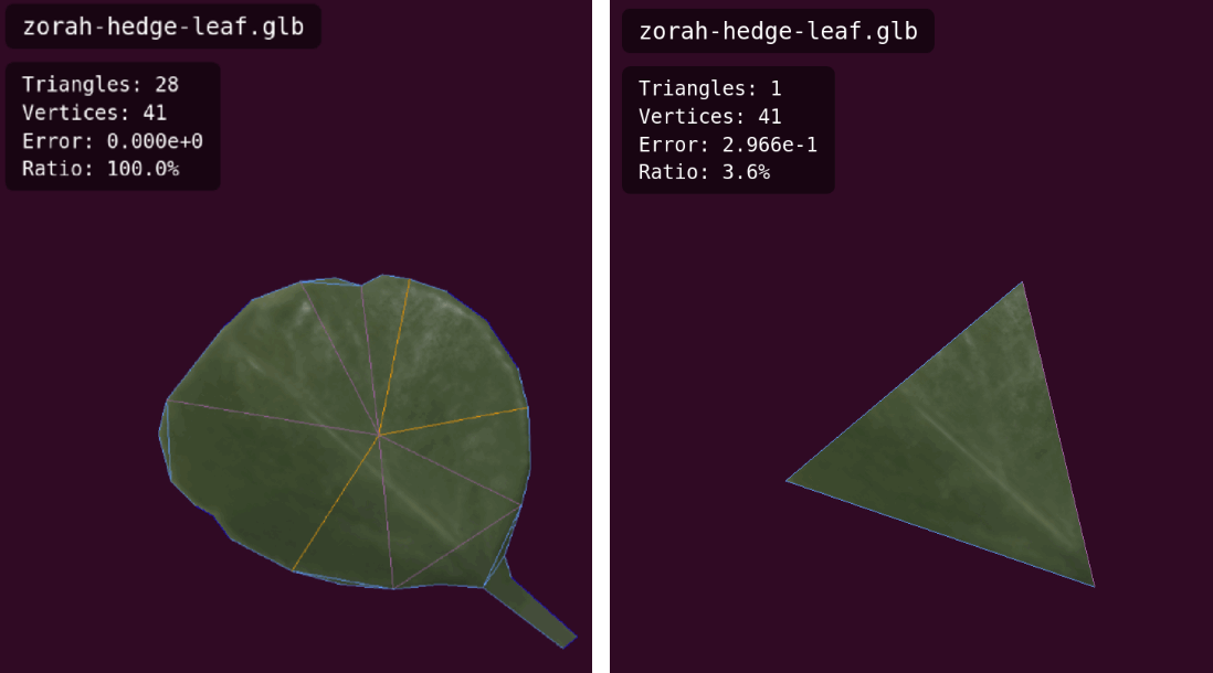
Zorah uses a very… geometric approach to modeling foliage; all leaves that you see in the scene have many triangles for each individual leaf, and while at times there’s also a texture with a bit of an alpha, the models are quite detailed. For example, here’s a single leaf, extracted out of a 3.8M triangle mesh of a hedge cover; the high resolution version has 28 triangles here, with the automatically simplified version on the right:
Now, all of this by itself is not a problem, other than seeming delightfully excessive; after all, the whole point of the hierarchical clustered LOD is that we take way too many triangles and process them into a representation that can simplify the result down to any number of triangles, no matter how small. However, foliage in particular presents a problem due to how simplification typically works.
Up until a point, the leaf simplifies normally, and the simplifier can go all the way from the original leaf to just a single triangle, pictured above. There is already a little bit of a problem here but it does not become critical until later, so I’ll cover that below. However, let’s say you started from a hedge mesh that had 130K leaves, each with 28 triangles. Simplifying this down to ~130K triangles is “easy”: each leaf becomes a triangle. However, 130K is still too many triangles, and if a hedge is just a few thousand pixels on screen, we’d like to go further. Once every leaf has been simplified to a single triangle, the only possible next step the simplifier can take is to remove individual leaves. And this is exactly what we get - subsequent levels of detail get fewer and fewer leaves, which results in the entire hedge eroding. Below you can see two screenshots taken in rasterization mode (to make it easier to see); on the left screenshot, the hedge on the left is mostly intact, but the hedges along the wall are already visibly eroded; the right screenshot is after pulling the camera further back, at which point the hedges become invisible.
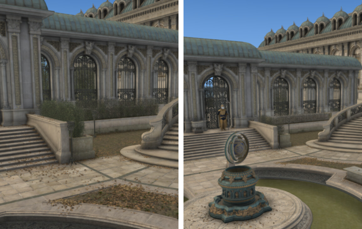
Now, this is partially related to the particular behavior of error metrics and how it interacts with the error threshold; but this post is getting long so I will omit some details here. Suffice it to say, this problem is fairly fundamental because the goal of Nanite is to replace clusters with simplified versions such that the error introduced by replacing individual triangles with their coarser versions is under a pixel. But that means that at a distance where each leaf’s triangle is under a pixel in size, every leaf should, logically speaking, be replaced by its simplified copy - which, in this case, is “no leaf”. Unfortunately, this also happens across the entire mesh, in an act of coordinated omission: every cluster looks approximately the same as any other cluster, has approximately the same error, and thus is quickly replaced with the version of the cluster where most leaves are removed.
One way to understand this is that the collapses of edges that simplify leaves lead to loss of visible area, which leads to loss of coverage: a simplified mesh covers fewer pixels far away. If you look at the original 28-triangle leaf, it’s obvious that the single-triangle version also lost area - just, this area loss is less catastrophic. It is possible to simplify individual leaves in a way that results in less area lost - I’ve experimented with a few “correct” ways to do that, where the simplifier reestablishes the boundary that was lost through collapses and adjusts the vertex position accordingly. This does help for the initial collapses a bit - leaves retain coverage for longer - but doesn’t really fix the problem, because there still comes a point where each leaf is a triangle, and the only way to progress is to remove the leaves outright.
Fortunately, Nanite implementation in Unreal Engine has a solution to this problem: meshes tagged with Preserve Area setting undergo additional post-processing during the simplification. After simplifying each cluster group - which at deeper levels would typically have a number of leaves to start with and end up with half as many, e.g. going from ~3000 leaves to ~1500 - they compute the total surface area before and after simplification, and restore the area by taking the boundary edges of the resulting geometry, and expanding the vertex positions outwards, dilating the edges. This retains coverage by redistributing surface area to surviving triangles; the result is that each successive layer of the cluster DAG gets fewer, bigger, leaves.
Now, redistributing area to surviving boundary is inherently dangerous: it may lead to severe outward expansion in unexpected cases. Nanite documentation says “This setting should be enabled on all foliage meshes and nothing else” - and indeed, enabling this indiscriminately can lead to artifacts, as it can translate lost surface area to surviving boundary, creating… interesting results. I was not happy with that tradeoff so I kept experimenting with various alternatives and ultimately settled on preserving the boundary area: that is, the area in boundary-adjacent triangles lost during simplification is redistributed to the open boundary of surviving triangles. This can still be imperfect but is much more selective and, generally speaking, could be enabled more widely - however there is still a risk of this redistribution creating significant geometric artifacts, so this is exposed as an opt-in clodConfig::simplify_dilate_borders, and vk_lod_clusters only sets this setting on meshes with two-sided geometry as a proxy for “foliage”.
From up close, the low detail geometry produced by this method looks pretty funny:
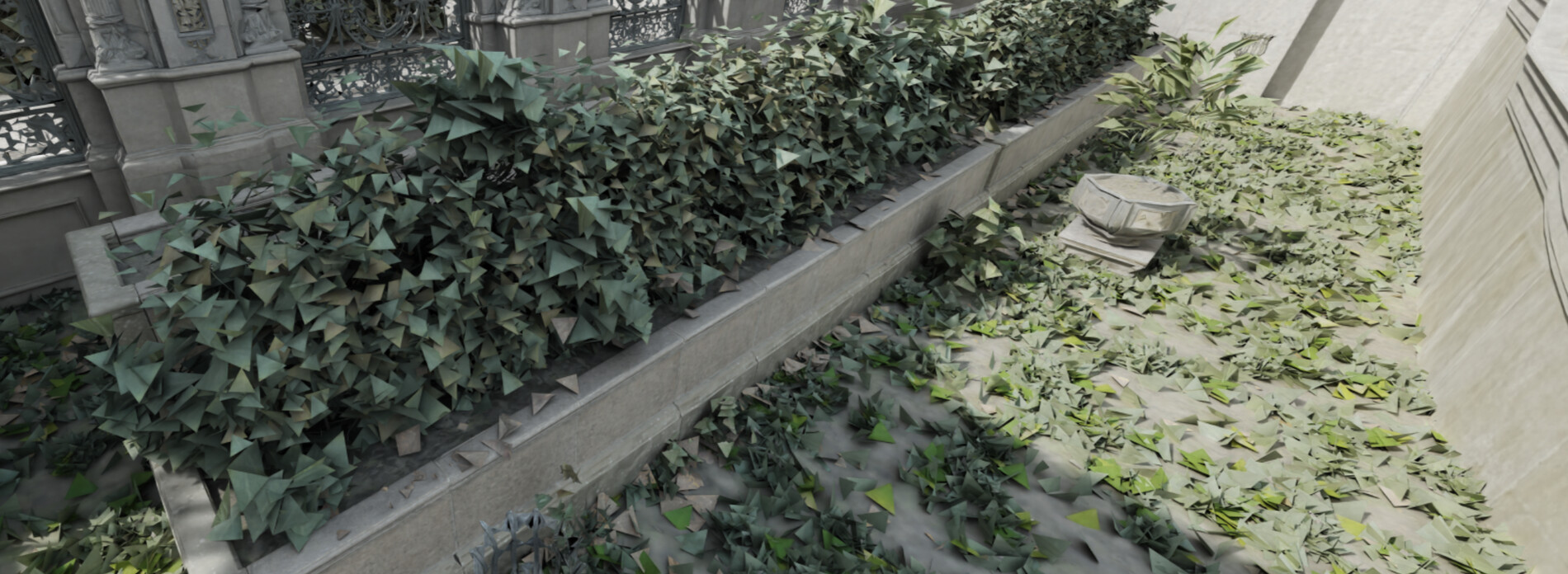
… however, the error tracked through the collapse sequence reflects the ideal distance to perform the switch, and from a far distance this mostly looks fine. Naturally this method doesn’t have a way to control for where exactly the coverage is lost and regained; the shape of trees far away may deform a bit, as some branches lose more leaves than others. This does seem like the best we could do with just triangle based LODs, but I am not surprised that Epic is working on a voxel-based system for foliage as ideally what you want here is a filterable representation, and triangle meshes are anything but. This technique does work for less… extreme… foliage, although for card-based trees expanding the card boundary edges may result in odd looking branches from far away if they were baked into the texture.
Now, this is currently implemented “manually” inside clusterlod.h using the aforementioned option, and is not part of meshoptimizer-the-library. Part of this is my hesitation with the method itself: it’s not carefully localized, and while my boundary area adjustment makes it much safer, it’s still less selective or precise than I would like, and definitely not rigorous unless you know your geometry is triangle-based foliage. Part of this is the API: in meshoptimizer, the natural place to add this would be as a flag on meshopt_simplifyWithUpdate API, which already updates vertex positions alongside other attributes for optimal appearance. However, clusterlod.h does not use simplifyWithUpdate and the code would require revision and reorganization to switch. So for now this is specific to clusterlod.h and you kinda have to know what you are doing when enabling this; but it can certainly make it to the core library in one shape or another if there’s sufficient interest in this addition.
Meshlet compression
With the foliage fix, this pretty much concludes the improvements since last time… except, I could not resist and tried one more thing.
After aforementioned processing, Zorah scene is saved to disk as a large number of clusters; each cluster has its own set of vertex data (positions and attributes), triangle and material indices, as well as various other streaming and culling related information. Each cluster is serialized in isolation; because of that, vertex codec is actually not a great fit, and vk_lod_clusters implements a variable bit delta encoding scheme for storing quantized vertex data instead; but the triangle index data is - or, rather, was - uncompressed.
The resulting file encodes ~3.26B triangles (around twice the original triangle count - which is exactly what you’d expect since every subsequent DAG level halves the triangle count, and 1 + 1/2 + 1/4 + ... = 2), and takes ~54.9 GB. Out of that, vertex data is ~41.9 GB (compressed from ~77.6), triangle indices take ~9.8 GB, and the rest is material indices (~1.15 GB) and other per-cluster and per-group data. The triangle indices represent a tiny index buffer (up to 128 triangles) for each cluster, that refers to vertices unique to that cluster, and are stored as 3 bytes per triangle - which is the format that you’d need to work with clustered raytracing as the driver expects a specific input layout.
Earlier this year, meshoptimizer gained a meshlet codec; similarly to vertex and index buffer codecs, it compresses and decompresses meshlet topology. While you could view the meshlet index data as a small index buffer, the existing index codec was not a good fit - it was built for long sequences of large indices, and the meshlet triangles were small in number but already fairly compact. The index codec was also simply not fast enough to decode; it was designed more than 9 years ago, for a very different set of use cases and I didn’t know as much about designing efficient-to-decode formats as I do now.
Additionally, while in some renderers meshlet index buffers are self-sufficient (as each cluster gets its own copy of vertex data), in others a global vertex index needs to be retrieved, so each meshlet requires both a list of triangle indices and an array of vertex references; these need to be compressed too.
So, I’ve set out to build a very efficient and compact meshlet topology compression format late last year, and it was shipped in meshoptimizer 1.1 in April. I’m very proud of the result; the decoder is incredibly fast, reaching up to 10 GB/s of decoding throughput on one CPU core depending on the specific configuration and data types; it’s also versatile, as it supports meshlets with or without vertex references, and can handle arbitrary meshlet configurations. The decoder uses unusual and mind-bending tricks that allow it to decode at this rate while maintaining reasonable compression ratios; and, as usual, the result can be post-compressed with your favorite general purpose codec. I do not have space here to do the codec justice; but, Zorah had 9.8 GB of indices on disk and that meant cluster streaming had to read more data - so this seemed like a perfect fit.
And a perfect fit it was; the integration was quite straightforward, and it compressed the triangle indices down to ~2.6 GB, or about 6.5 bits per triangle, reducing the final on-disk representation to 47.7 GB; an unrelated tweak to material index storage then resulted in a final size of 47.0 GB. Because the decoder is so fast, having to decompress the index data alongside the rest of the cluster during streaming is almost invisible in the profiler, and the decoder can target write-combined memory directly, so it’s a matter of calling one extra function during streaming decompression.

Notably, the resulting format is vendor-agnostic, and has no specific restrictions on cluster configuration or geometry storage; vk_lod_clusters happens to use 128-triangle clusters with up to 128 vertices, which works fine, and other configurations would work well too. Because it’s so fast to decode on the CPU it’s easy to integrate into existing streaming pipelines, with a lot of different options for how exactly to structure that integration (the vk_lod_clusters integration looks quite different from another renderer I have helped integrate this into); it can even be decoded on the GPU, although not directly from the mesh shaders - which wouldn’t apply to raytracing anyway.
The decision to store cluster-specific vertex data is also a tradeoff; while it works fine for vk_lod_clusters, it likely results in a significant amount of vertex duplication as boundaries between clusters at the same DAG level share vertex data, and different levels could also share vertex data in many cases. This is very convenient because it makes each cluster an independent unit that can be decoded during streaming in isolation; but other organization schemes are also possible, such as page-based storage where each page stores many clusters with vertex data shared across clusters, and per-cluster triangle indices with vertex references into the page vertices. Using this format would have some runtime implications though, especially for ray-tracing APIs that do not support vertex indirections; but it would be a good fit for rasterization, and the ray-tracing builds could copy vertex position data for each cluster as necessary in theory. I’m mentioning this not because this is the best, or even necessarily strictly better, solution, but just to note that in that case, you would use meshlet codec to compress both triangle indices and vertex references for each cluster - and perhaps compress page vertices with vertex encoder. Naturally, when streaming or clustered LOD is not a concern, the meshlet codec works well too; niagara renderer does that if you’re curious.
Conclusion
Clustered level of detail is a gift that keeps giving! At the end of the last post, clusterlod.h was in a somewhat half-ready state: has some features, doesn’t have some others that would probably be nice to add, probably works in more complex scenarios but who knows. With the work over the last year and especially this release, I’m quite happy with being able to just load the entire Zorah level (after a little under 4 minutes of processing time) and fly around on my measly 5070.
All of the changes described above are already part of meshoptimizer as of 1.3 release. And definitely check out vk_lod_clusters sample, read the code, play with the scene - there’s a lot of interesting runtime code there that I didn’t cover here, courtesy of NVIDIA engineering team.
What’s perhaps particularly nice is that out of everything I’ve written above, and things I haven’t written about but that are working towards a nice final result, almost nothing is actually specific to this system. The various compression schemes have been developed independently and even though clustered LOD was on my mind when working on meshlet codec, the main use cases for it do not need a cluster hierarchy; all of simplification changes are quite helpful with or without the cluster hierarchy; and even the foliage “hacks” can be applied to discrete LOD pipelines with similarly good results. meshoptimizer was created, and continues to be developed, as a collection of robust and versatile algorithms; single-purpose algorithms are nice sometimes, but to the extent you can mix and match them to build bigger, custom systems, the overall design is that much more useful - and the variety of components that were useful here makes me happy.
Should all engines embrace clustered level of detail? I’m still not sure. There’s a place for hierarchical continuous LOD but it’s not obvious to me that this is a vital, or the final, step; triangles continue to be suboptimal in many respects, and the extra complexities around managing billions of triangles are difficult to wave away. Loading 10M triangle models in Blender is not fun; runtime efficiency of these systems is often worse than potential alternatives we could have been building, and on-disk impact is non-trivial. And if you’ve played recent games you might have noticed geometry popping in cutscenes now and again. But - this is an interesting technology, it solves real problems, and it is fun to work on from time to time. I hope this remains just one of the many ways we build geometry rendering systems, with its own tradeoffs, and that we continue to find other interesting ways to model geometric detail.
Thanks to Christoph Kubisch for discussions, feedback, and vk_lod_clusters integration, to NVIDIA for sharing research, code and assets openly, and to Valve for sponsoring meshoptimizer development.
Appendix: Lossy compression
This is not part of the original Zorah scene; but I just want to show this to make this exposition more complete. In the glTF files discussed above, the vertex attributes (positions, normals, tangents, texture coordinates) are encoded with full 32-bit floating point precision. Typically data encoded like this has a lot of entropy that is pretty much impossible to remove when the goal is lossless compression; it’s particularly bad when storing unit-length vectors as most of the bits are simply irrelevant and yet take space, and also are difficult to predict.
Indeed, if we look at the lossless compression here, we can see that normals compress quite poorly. Tangents compress better but they have one fully predictable component (.w is either +1 or -1 and varies rarely); note the raw size for tangents is much smaller than it is for normals, which is because many meshes in this scene simply lack a tangent stream.
| Attribute | Raw | Lossless v1 |
|---|---|---|
| Positions | 14.3 GB | 8.9 GB (62.1%) |
| Normals | 14.3 GB | 11.7 GB (81.9%) |
| Tangents | 6.4 GB | 4.1 GB (64.1%) |
| UVs | 9.4 GB | 4.7 GB (50.0%) |
To fix this, you need to store quantized data, which is trivial for normals and tangents; and, additionally, you can apply vertex filters that allow you to store each individual component lossily and recover the original value when decoding. The vertex filters are another layer in the layered compression scheme; the fully stacked decompression pipeline looks like:
- General purpose decompression goes from heavily compressed bytes to encoded bytes
meshopt_decodeVertexBuffergoes from encoded bytes to pre-filtered bytesmeshopt_decodeFilter*goes from pre-filtered bytes to quantized bytes (in-place)- Shader/CPU dequantization goes from quantized bytes to floats
The filtered representation could also be decoded directly in the shader, although at that point you might be better off building a carefully tuned custom vertex representation. A big reason why vertex filters exist is that they integrate lossy compression in a more straightforward way that does not require changes to downstream consumers. In context of a custom game engine where you have full control of the data producers and consumers, they are perhaps less relevant; but they are incredibly effective in glTF-like scenarios where you have a more rigid format that you have to abide by.
With that in mind, let’s look at one possible configuration of lossy compression that could make sense here. Zorah scene processing code compresses the vertex data when storing it for runtime use, and that compression involves quantization; I would not necessarily recommend the double-quantization because it can carry extra precision loss, but for the purpose of this experiment let’s store the data as follows:
- Normals will use normalized integers and meshopt octahedral filter with 12 bits per component (a bit above what Zorah needs at runtime)
- Tangents will use normalized integers and meshopt octahedral filter with 8 bits per component (plenty precision in practice, although you might want to read Quantizing tangent frames for more variations that are interesting)
- Positions and texture coordinates will use floating-point, to avoid dealing with uniform quantization, but with meshopt exponential filter using
meshopt_EncodeExpSeparatewith 18 bits per component (likely excessive for UVs, but that’s whatvk_lod_clustersuses for runtime storage).
Note that we’re still operating within the confines of glTF specification: meshopt filters allow us to represent the data on disk in a transformed way that reduces entropy (e.g. octahedral storage for unit vectors is significantly better than storing components separately from the compression point of view), but they will decode data to a format all glTF loaders that support KHR_mesh_quantization should understand.
| Attribute | Raw | Lossless v1 | Lossy v1 |
|---|---|---|---|
| Positions | 14.3 GB | 8.9 GB (62.1%) | 5.8 GB (40.6%) |
| Normals | 14.3 GB | 11.7 GB (81.9%) | 3.3 GB (23.4%) |
| Tangents | 6.4 GB | 4.1 GB (64.1%) | 0.8 GB (12.6%) |
| UVs | 9.4 GB | 4.7 GB (50.0%) | 3.5 GB (37.8%) |
This is much better, and allows us to store the entire geometry for the scene in ~15.3 GB (13.4 GB of vertex data and 1.9 GB of index data) - a bit less than half of the losslessly compressed representation; which could be compressed further with Zstd if necessary, as usual. And again this is the most lenient version; if I were tuning this more carefully for production, I’d probably use a little fewer bits for UVs (e.g. 14), and meshopt_EncodeExpSharedComponent mode for both positions and UVs, which would save a couple extra gigabytes for a grand total of 13.2 GB glTF data, and still decompress at gigabytes per second per core.
- Because the extension is defined on buffer views and the vertex encoding itself is lossless, it’s easy to recompress existing files by decompressing their v0 representation, re-encoding using
meshopt_encodeVertexBufferinto v1 and updating the extension to KHR - without having to analyze the scene deeply. - If you remove attributes, v0 positions + indices in the table above would add up to ~11 GB, and yet I said that the attribute-less version is just 9 GB. That is probably because the attribute-less version can do a more aggressive reindexing and get fewer vertices to encode; the data above contains vertices that have the same position but different attributes, so it may need to encode some positions twice.
- I’m using Zstandard here as an example, as it’s a state of the art open-source compressor that is often used to store assets on disk; the same logic may or may not apply to other compressors. For example, LZ4 is faster to decompress than meshopt codecs - but usually results in significantly lower compression ratios on mesh data.
- If you are using simplification on the entire mesh, you can simply pass
meshopt_SimplifyPruneas an extra option, and small connected components will be automatically discarded alongside simplified geometry. But that requires analyzing the entire mesh and simultaneously removing many triangles, whereasclusterlod.hsimplifies cluster groups individually. - Last year I was using GeForce RTX 3050 for these tests - good enough to do basic testing but not exactly practical to render a path traced scene with a reasonable resolution ;)
- It’s a little difficult to precisely understand the memory requirements here; this sample uses DLSS which allocates some unknown amount of memory for the models and internal buffers; and, resizing the window has to reallocate a number of buffers while keeping the previous buffers in flight, which adds to the high memory watermark.
- Which was first published in 1999; to my knowledge, nothing better has been invented since - which is a common story for simplification, where the best ideas are 25 years old by now.
- As Hyrum’s law teaches us, it does not matter what contracts you promise to uphold; users will rely on observed behavior, build expectations around it, and get upset when that behavior changes. Obligatory xkcd
- If you are interested in a temporary solution, the code I posted last year should still work well for this.
- I can’t share screenshots from my experiments, but for example if you apply this to a tree trunk that happens to be in a separate mesh, simplification would often reduce the surface area of the trunk, and the dilation logic can redistribute the lost area to an open boundary where the trunk would leave a hole for a branch - resulting in visible and unnecessary geometric extrusion.
- The codec has fixed-size overhead which results in suboptimal compression if you use it on short streams with small vertices; the runtime decoding overhead also amortizes poorly as it was never tuned for extremely frequent invocations.
- Using a general purpose compressor on top of this can reduce this further; although this requires that multiple meshlets be compressed at once to amortize the various framing overheads, which would also be easier with the page-based storage covered below.
- Direct mesh shader decoding and vendor-specific formats in this area come with too many tradeoffs that make them hard to recommend, but that deserves a separate post.
- This is a bit longer than it took last year, but last year’s
vk_lod_clusterstimings (3m 20s) did not include attribute processing or any compression of the resulting data and were done on a slightly different scene variant. All the extra processing adds up, but still ends up being fairly fast, reprocessing the entire scene from scratch in ~3m 45s across 16 cores of an AMD Ryzen 7950X, running in 105W Eco mode. - This would require establishing per-mesh quantization grids and adding dequantization transforms via node matrices and
KHR_texture_transform, which requires extra material support; this is valuable if the goal is to minimize the final delivery size, but not worth the hassle here, and would not be a close match to the existing runtime format Zorah uses.

 点赞
点赞 收藏
收藏 点踩
点踩 分享
分享